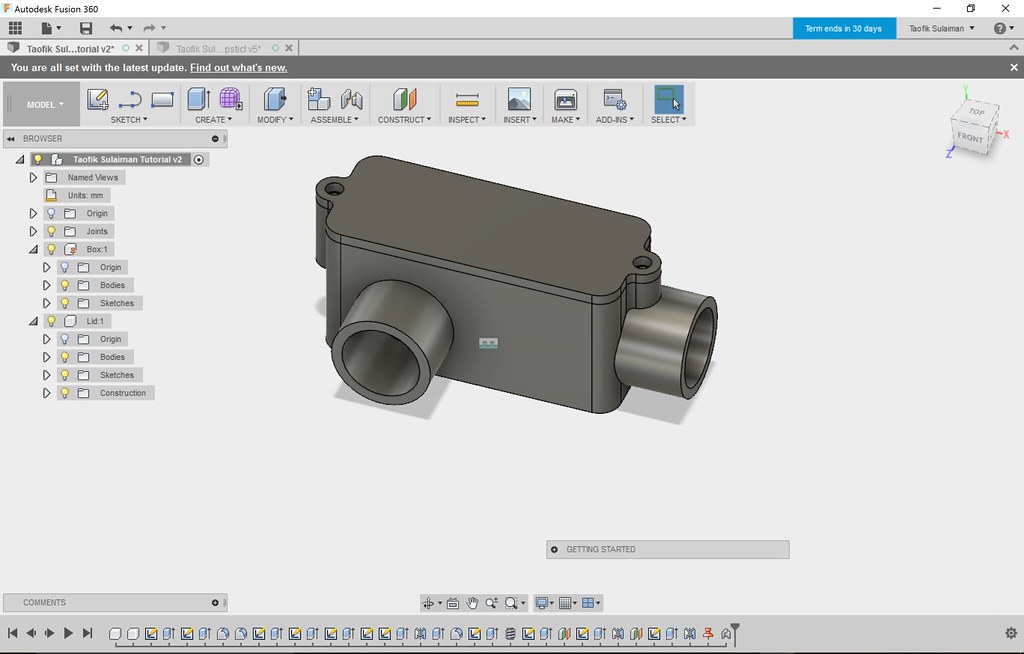

If you’re designing for a certain kind of screw or bolt, you can actually cut holes designed specifically for certain kinds of screws and bolts by selecting the “clearance” hole tap type. You also have the option to recess your opening for a counterbore or a countersink type screw head. If you don’t want your hole to go all the way through, you can also set it so that the end of the hole comes to a point. A lot of the time, you’re probably going to just drag your hole depth, but type a value for the diameter. These can be changed either by clicking and dragging the arrows or by typing values. You can adjust many things about the hole you’re creating – the simplest being the size and diameter. Now let’s take a look at the options for actually creating your hole. If your sketch is like mine, you may have to click the “flip direction” button to get your hole to be cut in your object. For that one, it’s going to ask you to select sketch points from your 2D sketch as reference points. You also have the ability to reference an object in your model, like an edge, and set a distance from that object using the reference selection.īefore we go any further, let’s take a quick look at the multiple holes option as well. It will also inference to any points you have in your body – for example, for this box, it inferences to the natural center point. Notice that you can drag the hole around to place it on any particular face. Whenever you click on the face, you’ll get this red preview of where the hole will be. So for example, in the case of this box, you’d select the top face. It’s going to ask you to set a plane from which you want to create your hole. Let’s take a look at the single hole placement option first. When you first activate the hole tool, you have two options – you can create a single hole, or you can select multiple holes based on different points in a sketch. However, if you use the built-in hole tool, you get access to a lot more different tools and functions than if you just cut a simple hole using an extruded circle. This is a totally valid way to cut holes and that’s not a bad thing. Now you could just draw a sketch circle then extrude it through an object and use the cut interaction. You’ll do this for a variety of reasons, including creating fasteners, openings, and more. One of the things you’ll be doing a lot of when working inside of Fusion 360 is cutting holes in objects. In today’s video, we’re going to discuss the hole tool – Fusion 360’s tool for cutting holes, adding threads, adding countersinks, and more!ĭo you like these Fusion 360 Tutorials? Make sure to subscribe to my YouTube channel to stay up to date on the newest videos! Subscribe Here – The Fusion Essentials YouTube Channel This article was originally published in 3D World, the world's best-selling magazine for CG artists.
#Autodesk fusion 360 tutorial software#
Finally, there is the cost, which is prohibitive for many 3D artists, who only use CAD software to convert models.

Not only this, but CAD software also differs in that it operates with precision in mind, rather than the more freeform creativity that can be achieved in 3D software.

The truth of the matter though, as many 3D artists are only too aware, is that CAD software is actually very different, using another modelling paradigm that utilises NURBS and volumes rather than subdivision surfaces, which are typically found in 3D software. When looking at a computer screen running CAD and digital content creation software, many people would likely find it difficult to tell them apart – they both make models that can then be moved and rotated around the screen. What's the difference between CAD and 3D software?

To access new features, such as the preview of the updated UI, which simplifies the toolsets for new users, you can go to the Preferences menu and select Preview > UI Preview in order to see the latest update. A good example is the user interface, which is in the process of being updated. One of the great things about Fusion 360 is the amount of work that Autodesk is putting in to constantly improve it. Click the icon in the top right to enlarge the image (Image credit: Autodesk / Mike Griggs)


 0 kommentar(er)
